


China's Cable Cutting Patent
New Details on China's Trickster Dredging

China In Arms BOOKSTORE and GIFT SHOP!
Follow on Twitter
Subscribe: $5 Month/$50 Annual (unable to secure a subscription contact the bank for permission for Stripe deposits).
15 January 2025 (Wednesday)
China's Cable Cutting Patent
New Details on China's Trickster Dredging
By Wendell Minnick (Whiskey Mike) 顏文德
TAIPEI - Below is a Chinese patent for locating undersea communication cables.
Recently, China has been accused of dredging and severing communication cables belonging to Taiwan and another in the Baltic Sea.
Strategists suggest China is practicing “grey zone” or “asymmetrical warfare” to prepare for an invasion of Taiwan.
Below is an English abstract of the above Chinese PDF:
CN117872484A
China
Other languages
Chinese
Inventor
Current Assignee
Guangdong Water Conservancy And Electric Power Survey Design And Research Institute Co ltd
Worldwide applications
2024 CN
Application CN202410078124.5A events
2024-01-19
2024-01-19
2024-04-12
Info
Priority and Related Applications
External links
Claims (10)
Hide Dependent
1. A method of detecting an underwater line comprising the steps of:
acquiring underwater topography data, metal pipeline data and/or nonmetal pipeline data;
and carrying out data correction on the underwater topography data, and calculating to obtain the position information of the target pipeline based on the corrected underwater topography data, the metal pipeline data and/or the nonmetal pipeline data.
2. The method of claim 1, wherein the step of collecting underwatertopography data, metal line data and/or non-metal line data comprises:
acquiring three-dimensional data of underwater topography by adopting a multi-beam sounding device;
obtaining the water depth a by detecting the length of a working cable of the receiving device;
collecting metal pipeline data at the position of the underwater silt surface by adopting a magnetic exploration method;
and acquiring nonmetal pipeline data at the underwater silt surface by adopting a ground penetrating radar method.
3. The method according to claim 1, wherein the step of performing data correction on the underwater topography data, calculating to obtain the position information of the target line based on the corrected underwater topography data and the metal line data, comprises the steps of:
performing bow deviation correction, roll correction and pitch correction on the underwater topography data, and establishing an underwater topography live-action three-dimensional model based on the corrected underwater topography data;
calculating the underwater position H of the target pipeline based on an underwater topography live-action three-dimensional model and collected metal pipeline data, wherein the underwatertopography live-action three-dimensional model comprises a distance H from a water surface to a silt surface 1 The acquired metal pipeline data comprise the underwater magnetic field strength H of the target pipeline S And a sludge thickness d on the target line;
according to the distance h from the water surface to the silt surface 1 Correcting the water depth a, a=h in real time 1 。
4. A method according to claim 3, wherein the step of acquiring underwater topography data and metal line data further comprises:
when the target pipeline is a river-crossing pipeline and/or a river-crossing pipeline, acquiring land position information of the target pipeline through a GPS or a database; determining a detection water area of the target pipeline and the trend of the target pipeline based on the land position information of the target pipeline; and establishing a two-dimensional coordinate system by taking the trend of a target pipeline in the detection water area as the x-axis direction and the water flow direction or the water flow opposite direction as the y-axis direction, and moving in the detection water area according to a preset track and collecting underwater topography data and metal pipeline data.
5. A method according to claim 3, wherein the step of calculating the target line underwater location H based on the underwatertopography live stock three-dimensional model and the acquired metal line data comprises the steps of:
underwater magnetic field intensity H based on underwatertopography live-action three-dimensional model and acquired SAnd the sludge thickness d, calculating the burial depth H of the target pipeline at the water bottom and the underwater magnetic field strength H S
The method comprises the following steps:
wherein K is a constant; beta is ocean current and salinity constant; h is the water bottom burial depth, namely the distance from the silt surface on the target pipeline to the target pipeline through the water bottom soil layer and/or the rock layer; lambda is the sludge constant; d is the thickness of the sludge; s is the horizontal distance between the detection point and the target pipeline; collecting the underwater magnetic field intensity corresponding to the horizontal distance between each detection point and the target pipeline, and establishing a set { (S) 1 ,Hs 1 ),(S 2 ,Hs 2 )(S 3 ,Hs 3)……(S n ,Hs n )};
Obtaining the maximum underwater magnetic field intensity H by adopting a Gaussian fitting equation Smax And obtain and maximize the magnetic field strength H Smax Corresponding water bottom burial depth h max Combining the distance h from the water surface to the sludge surface 1 Calculating the underwaterposition H of the target pipeline: h=h max +h 1 。
6. The method of claim 5, wherein the steps further comprise:
obtaining the maximum underwater magnetic field strength H Smax And the magnetic field intensity collected by the detection point when the horizontal distance S between the detection point and the target pipeline is half of the water bottom burial depthhSolving the ratio of the two, and calculating to obtain the water bottom buried depth h' with higher accuracy:
wherein t is a constant.
7. An underwater line detection system for implementing the method of any of claims 1-6, comprising;
the underwater data acquisition module is used for acquiring underwater topography data, metal pipeline data and/or nonmetal pipeline data; the control module is connected with the underwater data acquisition module and is used for carrying out data correction on underwater topography data and calculating and obtaining the position information of the target pipeline based on the corrected underwater topography data, metal pipeline data and/or nonmetal pipeline data; the underwater data acquisition module comprises:
the multi-beam sounding device is used for acquiring three-dimensional data of underwater topography; and the detection receiving device is connected with the control module, performs lifting adjustment according to the instruction of the control module and collects metal pipeline data and/or nonmetal pipeline data.
8. The system of claim 7, wherein the underwater data acquisition module further comprises:
the data storage module is used for storing the underwatertopography data, the metal pipeline data and the nonmetal pipelinedata acquired by the underwater data acquisition module; and the communication module is used for sending the data in the data storage module to the control module.
9. The system according to any one of claims 7-8, wherein the underwater data acquisition module is an unmanned survey vessel, the multi-beam sounding device is arranged at the bottom of the unmanned survey vessel, and the detection receiving device is connected with the unmanned survey vessel for acquiring metal pipeline data at the underwater silt surface by using a magnetic prospecting method and non-metal pipeline data at the underwatersilt surface by using a ground penetrating radar method.
10. The system of claim 7, wherein the control module comprises:
the data calculation module is used for calculating the underwatermagnetic field intensity according to the underwater topography three-dimensional data acquired by the multi-beam sounding device and the metal pipeline data acquired by the detection receiving device to acquire the target metal pipeline position; and the result display module is used for displaying the calculated underwater magnetic field intensity and the historical data.
Underwater pipeline detection method and system
Abstract
The invention discloses a method and a system for detecting an underwater pipeline, wherein the method comprises the following steps: collecting underwater topography data, metal pipeline data and/or nonmetal pipeline data; and carrying out data correction on the underwater topography data, and calculating to obtain the position information of the target pipeline based on the corrected underwater topography data, the metal pipeline data and/or the nonmetal pipeline data. When the pipeline in the detection water area is covered with more silt and the water bottom is deeper, the invention can determine the position and the burial depth of the pipeline; the invention can also realize the detection of metal and nonmetal pipelines at the same time, and effectively improves the detection efficiency and the detection precision.
Classifications
G01V3/08 Electric or magnetic prospecting or detecting; Measuring magnetic field characteristics of the earth, e.g. declination, deviation operating with magnetic or electric fields produced or modified by objects or geological structures or by detecting devices
Description
Underwater pipeline detection method and system
Technical Field
The invention belongs to the technical field of pipeline detection, and particularly relates to an underwater pipeline detection method and system.
Background
The underwater pipeline detection technology is a new technology developed along with the rising of underwater engineering, and in recent years, various submarine cable projects, pipeline projects, bridge tunneling projects, port pool projects on the shore and the like are started, and various islands are filled with sea and land, various networks are connected, and marine environments, resource investigation, protection and the like are started. Engineering services such as submarine cable construction, burying, detection, maintenance, submarine cable routing investigation and operation and maintenance detection are rapidly increasing. The submarine pipelinefaces complex and changeable ocean environments, is influenced by natural factors such as stormy waves, ocean currents, storm tides and the like, and artificial factors such as sand production, anchor damage and the like, potential safety hazards such as exposed pipelines and suspended spans easily occur, the submarine pipeline is exposed for a long time, fatigue fracture is extremely easy to occur under the impact of the stormy waves and the ocean currents, once accidents such as leakage and the like occur in the submarine pipeline, production is stopped, the ocean environments are polluted, ecological disasters are caused, and personal casualties and huge economic losses are even caused by explosion. It is important to precisely and effectively determine the position burial depth of the underwaterpipeline.
At present, the widely adopted underwater cable detection method mainly comprises the following steps: acoustic pipeline detection, multi-beam side-scan sonar detection, magnetic detection, underwater Robot (ROV) imaging, diver diving photographing, etc. However, when the above-mentioned conventional detection method is used to detect the position and depth of the pipeline when the pipeline is laid for a long time in the water and the mud is covered on the pipeline more.
Disclosure of Invention
In order to overcome the technical defects, the invention provides the underwater pipeline detection method and the underwater pipeline detection system, which can determine the position and the buried depth of the pipeline when the pipeline in the detection water area is covered with more silt, realize the detection of the metal pipeline and the nonmetal pipeline, and improve the detection efficiency and the detection precision.
In order to solve the above problems, a first aspect of the present invention provides a method for detecting an underwater line, comprising the steps of:
acquiring underwater topography data, metal pipeline data and/or nonmetal pipeline data;
and carrying out data correction on the underwater topography data, and calculating to obtain the position information of the target pipeline based on the corrected underwater topography data, the metal pipeline data and/or the nonmetal pipeline data.
Optionally, the step of collecting underwater topography data, metal line data and/or non-metal line data comprises:
acquiring three-dimensional data of underwater topography by adopting a multi-beam sounding device; obtaining the water depth a by detecting the length of a working cable of the receiving device; collecting metal pipeline data at the position of the underwater silt surface by adopting a magnetic exploration method; and acquiring nonmetal pipeline data at the underwater silt surface by adopting a ground penetrating radar method.
Optionally, the step of performing data correction on the underwatertopography data, and calculating to obtain the position information of the target pipeline based on the corrected underwater topography data and the metal pipeline data, includes the steps of:
performing bow deviation correction, roll correction and pitch correction on the underwater topography data, and establishing an underwater topography live-action three-dimensional model based on the corrected underwatertopography data; calculating the underwater position H of the target pipeline based on an underwater topography live-action three-dimensional model and collected metal pipeline data, wherein the underwater topography live-action three-dimensional model comprises a distance H from a water surface to a silt surface 1 The acquired metal pipeline data comprise the underwatermagnetic field strength H of the target pipeline S And a sludge thickness d on the target line; according to the distance h from the water surface to the silt surface 1Correcting the water depth a, a=h in real time 1 。
Optionally, the step of acquiring underwater topography data and metal pipeline data further comprises:
when the target pipeline is a river-crossing pipeline and/or a river-crossing pipeline, acquiring land position information of the target pipeline through a GPS or a database; determining a detection water area of the target pipeline and the trend of the target pipeline based on the land position information of the target pipeline; and establishing a two-dimensional coordinate system by taking the trend of a target pipeline in the detection water area as the x-axis direction and the water flow direction or the water flow opposite direction as the y-axis direction, and moving in the detection water area according to a preset track and collecting underwater topography data and metal pipeline data.
Optionally, the step of calculating the underwater position H of the target pipeline based on the underwater topography live-action three-dimensional model and the collected metal pipeline data includes the steps of:
underwater magnetic field intensity H based on underwater topography live-action three-dimensional model and acquired S And the sludge thickness d, calculating the water bottom burial depth H of the target pipeline and the underwater magnetic field strength H S The method comprises the following steps:
wherein K is a constant; beta is ocean current and salinity constant; h is the water bottom burial depth, namely the distance from the silt surface on the target pipeline to the target pipeline through the water bottom soil layer and/or the rock layer; lambda is the sludge constant; d is the thickness of the sludge; s is the horizontal distance between the detection point and the target pipeline; collecting the underwater magnetic field intensity corresponding to the horizontal distance between each detection point and the target pipeline, and establishing a set { (S) 1 ,Hs 1 ),(S 2 ,Hs 2 )(S 3 ,Hs 3 )……(S n ,Hs n )};
Obtaining the maximum underwater magnetic field intensity H by adopting a Gaussian fitting equation Smax And obtain and maximize the magnetic field strength H Smax Corresponding water bottom burial depth h max Combining the distance h from the water surface to the sludge surface 1 Calculating the underwater position H of the target pipeline: h=h max +h 1 。
Optionally, the steps further include:
obtaining the maximum underwater magnetic field strength H Smax And the magnetic field intensity collected by the detection point when the horizontal distance S between the detection point and the target pipeline is half of the water bottom burial depth hSolving the ratio of the two, and calculating to obtain the water bottom buried depth h' with higher accuracy:
wherein t is a constant.
The second aspect of the invention provides an underwater pipelinedetection system, which can realize the underwater pipeline detection method, comprising the following steps of; the underwater data acquisition module is used for acquiring underwatertopography data, metal pipeline data and/or nonmetal pipeline data; the control module is connected with the underwater data acquisition module and is used for carrying out data correction on underwatertopography data and calculating and obtaining the position information of the target pipeline based on the corrected underwater topography data, the corrected metal pipeline data and the corrected nonmetal pipeline data; the underwater data acquisition module comprises:
the multi-beam sounding device is used for acquiring three-dimensional data of underwater topography;
and the detection receiving device is connected with the control module, performs lifting adjustment according to the instruction of the control module and collects metal pipeline data and/or nonmetal pipeline data.
Optionally, the underwater data acquisition module further comprises:
the data storage module is used for storing the underwater topography data, the metal pipeline data and the nonmetal pipeline data acquired by the underwater data acquisition module;
and the communication module is used for sending the data in the data storage module to the control module.
Optionally, the underwater data acquisition module is an unmanned survey ship, the multi-beam sounding device is arranged at the bottom of the unmanned survey ship, and the detection receiving device is connected with the unmanned survey ship and is used for acquiring metal pipeline data at the underwater silt surface by adopting a magnetic prospecting method and acquiring nonmetal pipeline data at the underwater silt surface by adopting a ground penetrating radar method.
Optionally, the control module includes:
the data calculation module is used for calculating the underwater magnetic field intensity according to the underwater topography three-dimensional data acquired by the multi-beam sounding device and the metal pipeline data acquired by the detection receiving device to acquire the target metal pipeline position; and the result display module is used for displaying the calculated underwater magnetic field intensity and the historical data.
Compared with the prior art, the invention has the following beneficial effects:
the invention discloses a method and a system for detecting an underwaterpipeline, which are characterized in that underwater topography data, nonmetal pipeline data and metal pipeline data are obtained firstly; and carrying out data correction on the underwater topography data, and calculating to obtain the position information of the target pipeline based on the corrected underwater topography data, the metal pipeline data and/or the nonmetal pipeline data. When the pipeline is laid for a long time and the mud is covered on the pipeline in the detection water area, the invention can correct the influence of environmental factors such as the mud on the pipeline detection measurement, obtain the position information of the pipeline, and can detect the metal pipeline and the nonmetal pipeline at the same time, thereby improving the detection efficiency and the detection precision.
Drawings
The invention is described in further detail below with reference to the attached drawing figures, wherein:
[See PDF for FIG 1-13]
FIG. 1 is a flow chart of the method described in example 1;
FIG. 2 is a schematic diagram of steps S13-S18 of the method described in example 1;
FIG. 3 is a three-dimensional model of an underwater topography live view created by the method described in example 1 based on three-dimensional data of the underwater topography acquired by the multi-beam depthsounding device;
FIG. 4 is a graph of the distance of the detection point G1 from the target line level and the underwater magnetic field strength obtained by the methoddescribed in example 1;
FIG. 5 is a graph of the distance of the detection point G2 from the target line level and the underwater magnetic field strength obtained by the methoddescribed in example 1;
FIG. 6 is a graph of the distance of the detection point G3 from the target line level and the underwater magnetic field strength obtained by the methoddescribed in example 1;
FIG. 7 is a graph of the distance of the detection point G4 from the target line level and the underwater magnetic field strength obtained by the methoddescribed in example 1;
FIG. 8 is a graph of the distance of the detection point G5 from the target line level and the underwater magnetic field strength obtained by the methoddescribed in example 1;
FIG. 9 is a graph showing the position of an underwater pipeline obtained by calculation of data collected at five measurement points in a detected water area by using the conventional method and the method described in example 1;
fig. 10 is an image of an ultra-high pressure river-crossing gas pipe 1001 detected by the method described in example 1;
FIG. 11 is a schematic diagram of the system according to embodiment 2;
FIG. 12 is a schematic diagram of a detection using the system described in example 2;
FIG. 13 is a schematic diagram of a result display module of the system described in example 2;
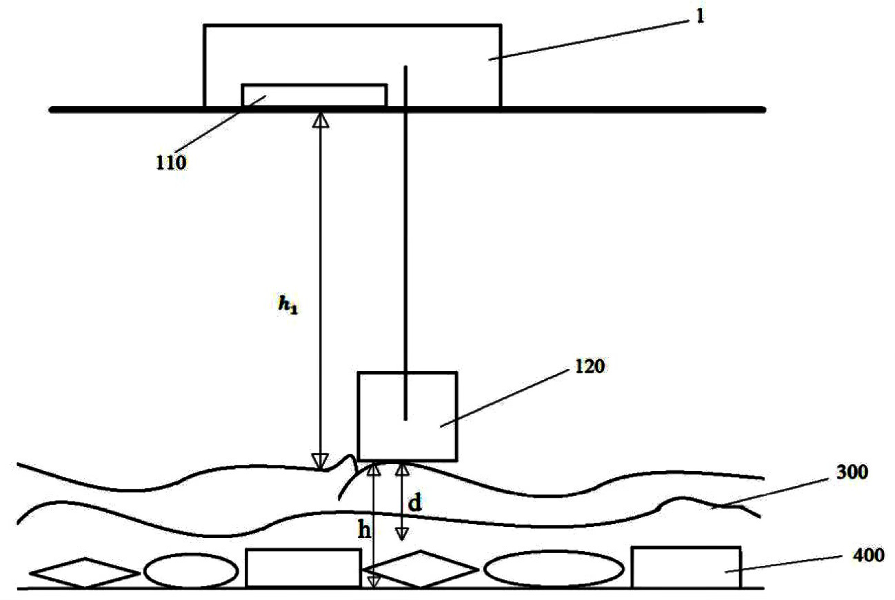
marking: 1. an underwater data acquisition module; 110. a multi-beam sounding device; 120. a probe receiving device; 130. a data storage module; 140. a multi-beam sounding device; 2. a control module; 210. a data calculation module; 220. a result display module; 300. a silt surface on the target pipeline; 400. a layer of water and/or rock; 500. a target line; 1001. the ultra-high pressure river-crossing gas pipe obtained by detection in the method described in example 1.
Detailed Description
The following description of the embodiments of the present invention will be made clearly and completely with reference to the accompanying drawings, in which it is apparent that the embodiments described are only some embodiments of the present invention, but not all embodiments. Embodiments of the present invention are intended to be within the scope of the present invention as defined by the appended claims.
In order that the above-recited objects, features and advantages of the present invention will become more readily apparent, a more particular description of the invention will be rendered by reference to the appended drawings and appended detailed description.
Example 1
As shown in fig. 1, the embodiment discloses a method for detecting an underwater pipeline, which comprises the following steps:
s1, collecting underwater topography data, metal pipeline data and/or nonmetal pipeline data.
Specifically, step S1 includes:
acquiring three-dimensional underwater topography data by adopting a multi-beam sounding device, wherein the three-dimensional underwatertopography data comprises a distance h from a water surface to a silt surface 1 。
The water depth a is obtained by detecting the length of the working cable of the receiving means.
Collecting metal pipeline data by using a magnetic prospecting method, wherein the metal pipeline data comprises the underwater magnetic field intensity H of a target pipeline S And the sludge thickness d on the target line.
And acquiring nonmetal pipeline data by adopting a ground penetrating radar method.
In one embodiment, when the target pipeline is a metal pipeline, step S1 includes:
s11, when the target pipeline is a river-crossing pipeline and/or a river-crossing pipeline, acquiring land position information of the target pipelinethrough a GPS or a database, and determining points M (x) of the target pipeline on two sides m ,y m ) And N (x) n ,y n )。
S12, based on the point M (x m ,y m ) And N (x) n ,y n ) And determining the trend of the target pipeline and the detection water area of the target pipeline.
S13, as shown in FIG. 2, a two-dimensional coordinate system is established by taking the trend of a target pipeline in the detected water area as the x-axis direction and the water flow direction or the water flow opposite direction as the y-axis direction, and an underwater data acquisition module, such as an unmanned survey ship, is controlled to periodically move in the detected water area according to a preset track and acquire underwatertopography data and metal pipeline data.
S14, presetting a longitudinal detection distance S and a transverse detection distance D of the unmanned survey vessel in a detection water area, randomly placing an unmanned survey vessel at one point in the detection water area, and automatically moving to a position with a distance from an x axis equal to the longitudinal detection distance S when the unmanned survey vessel automatically detects that the distance from the x axis is not equal to the longitudinal detection distance S, wherein the position is denoted as a point P (x) p ,y p )。
S15, the unmanned survey vessel moves along the water flow direction to detect, and three-dimensional data of underwater topography and metal pipeline data are collected. When the unmanned survey vessel moves to the intersection point with the x axis, the unmanned survey vessel continues to move along the water flow direction for data acquisition by the longitudinal detection distance S, and the intersection point is marked as a point E (x e ,y e ):
S16, stopping the unmanned survey vessel after continuously moving along the water flow direction for a longitudinal detection distance SStop advancing and mark this as point a (x a ,y a ) The method comprises the steps of carrying out a first treatment on the surface of the The unmanned survey vessel in turn moves in the x-axis direction a transverse probe distance D and stops moving forward, and this point is designated as point B (x b ,y b ):
S17, after the unmanned survey vessel moves a longitudinal detection distance S along the y-axis direction from the point B, an intersection point exists between the unmanned survey vessel and the x-axis, and the intersection point is marked as a point F (x f ,y f ):
S18, the unmanned survey vessel continues to move along the y-axis direction from the point B for a longitudinal detection distance S, stops advancing, and marks the point as a point C (x c ,y c ) The method comprises the steps of carrying out a first treatment on the surface of the The unmanned survey vessel in turn moves in the x-axis direction a transverse probe distance D and stops moving forward, and this point is designated as point D (x d ,y d ):
Repeating the steps S15-S18, and periodically moving the unmanned survey vessel in the detection water area to acquire underwater topography data and metal pipeline data.
In one embodiment, the distance to the shore point N is determined when the unmanned survey vessel is periodically moved in the survey water and past point E or the periodic point of point E.
Taking point E as an exampleWhen the unmanned survey vessel periodically moves in the detection water and passes through the point E, the distance between the point E and the opposite shore point N is calculatedAnd determine the distance L EN Relationship to the lateral detection distance D. If L EN If the number is less than or equal to D, the unmanned survey vessel is considered to be close to the shore, and the unmanned survey vessel is controlled to stop working; otherwise, controlling the unmanned survey vessel to continue working for data acquisition.
In one embodiment, the distance to the shore point N is determined when the unmanned survey vessel is periodically moved in the survey water and past point F or the periodic point of point F.
Taking the point F as an example, when the unmanned survey vessel periodically moves in the detection water and passes through the point F, the distance between the point F and the opposite point N is calculatedAnd determine the distance L FN Relationship to the lateral detection distance D. If L FN If the number is less than or equal to D, the unmanned survey vessel is considered to be close to the shore, and the unmanned survey vessel is controlled to stop working; otherwise, controlling the unmanned survey vessel to continue working for data acquisition.
S2, carrying out data correction on the underwater topography data, and calculating to obtain the position information of the target pipeline based on the corrected underwater topography data, the metal pipeline data and/or the nonmetal pipeline data.
In one embodiment, when the target pipeline is a metal pipeline, step S2 includes:
performing bow deviation correction, roll correction and pitch correction on the underwater topography data, and establishing an underwater topography live-action three-dimensional model based on the corrected underwatertopography data, as shown in fig. 3;
calculating the underwater position H of the target pipeline based on an underwater topography live-action three-dimensional model and collected metal pipeline data, wherein the underwater topography live-action three-dimensional model comprises a distance H from a water surface to a silt surface 1 The acquired metal pipeline data comprise the underwatermagnetic field strength H of the target pipeline S And the sludge thickness d on the target line.
Because the detection receiving device does not move synchronously with the unmanned measuring vessel, certain hysteresis exists, and certain error exists in the water depth obtained by the length of the operation cable of the detection receiving device, the distance h from the water surface to the silt surface can be measured 1 Correcting the water depth a, a=h in real time 1。
Specifically, based on underwater topography live-action three-dimensional model, the acquired underwater magnetic field intensity H S And the sludge thickness d, calculating the water bottom burial depth H of the target pipelineand the underwater magnetic field strength H S The method comprises the following steps:
wherein K is a constant; beta is ocean current and salinity constant; h is the water bottom burial depth, namely the distance from the silt surface on the target pipeline to the target pipeline through the water bottom soil layer and/or the rock layer; lambda is the sludge constant; d is the thickness of the sludge; s is the horizontal distance between the unmanned measuring ship and the target pipeline.
Collecting the underwater magnetic field intensity of the unmanned survey vessel corresponding to the horizontal distance between each detection point and the target pipeline, and establishing a set { (S) 1 ,Hs 1 ),(S 2 ,Hs 2 )(S 3 ,Hs 3 )……(S n ,Hs n )};
Obtaining the maximum underwater magnetic field intensity H by adopting a Gaussian fitting equation Smax And obtain and maximize the magnetic field strength H Smax Corresponding water bottom burial depth h max Combining the distance h from the water surface to the sludge surface 1 Calculating the underwater position H of the target pipeline: h=h max +h 1 。
Specifically, in order to obtain a higher accuracy of the water bottom burial depth h':
obtaining the maximum underwater magnetic field strength H Smax And the horizontal distance S between the unmanned measuring vessel and the target pipeline is half of the water bottom burial depth hThe unmanned survey vessel is at the underwater magnetic field intensity that this gathered +.>Solving the ratio of the two, and calculating to obtain the water bottom buried depth h' with higher accuracy:
wherein t is a constant, when the initially calculated water bottom burial depth h is less than or equal to 3m, t=0.90, and the horizontal distance S between the unmanned measuring ship and the target pipeline is half of the water bottom burial depth hWhen in use, the intensity of the underwatermagnetic field is->Just the maximum underwater magnetic field strength H Smax 0.90 of (2); when the preliminary calculated water bottom burial depthh>When 3m, t=0.81, and the horizontal distance S between the unmanned measuring vessel and the target pipeline is half of the water bottom burial depth h +.>When in use, the intensity of the underwater magnetic field is->Just the maximum underwater magnetic field strength H Smax 0.81 of (2).
As shown in fig. 4-8, the magnetic field intensity curves acquired by the underwater detection method provided by the application through five measurement points G1-G5 in the detection water area by the unmanned measuring ship are obtained. As shown in fig. 9, for comparing the positions of the underwater pipelines obtained by calculating the data collected by the five measurement points in the detected water by using the conventional method and the underwater detection method provided by the application, it is known that the positions of the underwater pipelines obtained by calculating the underwater detection method provided by the application are closer to the actual positions of the pipelines than the conventional method, and the positions of the underwater pipelines obtained by calculating the depth h' of the water bottom with higher accuracy are further closer to the actual positions of the pipelines. Fig. 10 is an image diagram of an ultra-high pressure river-crossing gas pipe 1 obtained by the underwater detection method provided by the application.
When more silt is covered on the pipeline in the detection water area and the water bottom is deeper, the underwater position of the target pipeline is obtained by calculating the underwater magnetic field intensity; and the underwater buried depth with higher accuracy can be obtained by calculating the ratio of the maximum underwater magnetic field strength to the underwater magnetic field strength when the horizontal distance between the unmanned measuring ship and the target pipeline is half of the underwater buried depth, so that more accurate underwater position information of the target pipeline is obtained, and the detection efficiency and detection accuracy of the pipeline position are improved. In addition, the invention can detect the nonmetallic pipeline by a ground penetrating radar method, so as to improve the detection efficiency of the pipeline.
Example 2
Based on the same inventive concept, the application also provides an underwater line detection system for realizing the above-mentioned underwater line detection method. The implementation of the solution provided by the system is similar to that described in the above method, so specific limitations in one or more embodiments of the underwater line detection system provided below may be found in the above limitations of the underwater line detection method, and will not be described in detail herein.
As shown in fig. 10 and 11, the present embodiment discloses an underwaterline detection system including an underwater data acquisition module 1 and a control module 2, wherein:
the underwater data acquisition module 1 is used for acquiring underwatertopography data, metal pipeline data and/or nonmetal pipeline data; the control module 2 is connected with the underwater data acquisition module 1 and is used for carrying out data correction on underwater topography data and calculating and obtaining the position information of the target pipelinebased on the corrected underwater topography data, metal pipeline data and/or nonmetal pipeline data.
Specifically, the underwater data acquisition module 1 includes a multi-beam sounding device 110 and a detection receiving device 120; the multi-beam sounding device 110 is used to acquire three-dimensional data of underwatertopography. The detection receiving device 120 is connected with the control module 2, performs lifting adjustment according to the instruction of the control module 2, and collects metal pipeline data and/or nonmetal pipelinedata.
Specifically, the underwater data acquisition module 1 further includes a data storage module 130 and a communication module 140, where the data storage module 130 is configured to store the data acquired by the multi-beam sounding device 110 and the detection receiving device 120; the communication module 140 is configured to send the data in the data storage module 130 to the control module 2.
In one embodiment, the underwater data acquisition module 1 is an unmanned survey vessel, the multi-beam sounding device 110 is arranged at the bottom of the unmanned survey vessel, the detection receiving device 120 is connected with the unmanned survey vessel, and the detection receiving device is closely connected with the underwater silt surface to be advanced and acquire metal pipeline data (such as the underwater magnetic field strength H of a target pipeline) at the underwater silt surface by adopting a magnetic exploration method S And the sludge thickness d) on the target pipeline, and acquiring nonmetal pipeline data at the underwatersludge surface by adopting a ground penetrating radar method, wherein the detection depth of the detection receiving device 120 is in the range of 0-30m.
In one embodiment, the control module 2 includes a data calculation module 210 and a result display module 220, where the data calculation module 210 is configured to obtain three-dimensional underwater topography data according to the multi-beam sounding device 110, where the three-dimensional underwater topography data includes a distance h from a water surface to a silt surface 1 And the underwater magnetic field strength H of the target line acquired by the probe receiving device 120 S And calculating the water bottom burial depth h of the target pipeline to obtain the position of the target metal pipeline, wherein the water bottom burial depth h is the distance from the silt surface 300 on the target pipeline to the target pipeline500 through the water bottom soil layer and/or the rock layer 400. As shown in fig. 12, the result display module 220 is used for displaying the calculated underwater magnetic field strength and the history data.
The control module controls the unmanned survey vessel to arrive in the detection water area for pipeline detection, and the multi-beam sounding device performs multiple measurements to acquire underwater topography information; the detection receiving device performs lifting adjustment according to the instruction of the control module, and collects metal pipeline data and/or nonmetal pipeline data. The underwater topography information, the silt thickness information, the underwater nonmetallic pipeline data and the underwater metallic pipeline data are all stored in the data storage module, the communication module sends the underwatertopography information, the silt thickness information, the underwaternonmetallic pipeline data and the underwater metallic pipeline data stored in the data storage module to the control module, the control module corrects the received underwater topography information, the silt thickness information, the underwater nonmetallic pipeline data and the underwatermetallic pipeline data by adopting an algorithm, and the positions and the burial depths of the nonmetallic pipelines and the positions and the burial depths of the metallic pipelines are obtained according to the processed data.
According to the underwater position detection method, the acquired underwater nonmetallic pipeline data and underwater metallic pipeline data are subjected to correction processing by adopting an algorithm, so that deviation influence caused by silt, ocean current and water temperature is reduced, and when more silt is covered on the pipeline in the detection water area and the water bottom is deep, the water bottom buried depth of the target pipeline can be obtained by calculating the underwater magnetic field intensity, so that the obtained underwater position is obtained; the underwater buried depth with higher accuracy can be obtained through calculation of the ratio of the maximum underwater magnetic field strength to the underwater magnetic field strength when the horizontal distance between the unmanned measuring ship and the target pipeline is half of the underwater buried depth, so that more accurate underwater position information of the target pipeline can be obtained; in addition, the invention can detect the metal pipeline and the nonmetal pipeline at the same time, thereby effectively improving the detection efficiency and the detection precision.
In the present specification, each embodiment is described in a progressive manner, and each embodiment is mainly described in a different point from other embodiments, and identical and similar parts between the embodiments are all enough to refer to each other.
The principles and embodiments of the present invention have been described herein with reference to specific examples, the description of which is intended only to assist in understanding the methods of the present invention and the core ideas thereof; also, it is within the scope of the present invention to be modified by those of ordinary skill in the art in light of the present teachings. In view of the foregoing, this description should not be construed as limiting the invention.
The present invention is not limited to the preferred embodiments, and any modifications, equivalent variations and modifications made to the above embodiments according to the technical principles of the present invention are within the scope of the technical proposal of the present invention.